
Device Panel
The Device Panel is a tool for interrogating individual devices that are in the Performance Workspace. The Device Panel works outside of the grouped controls and grouping rules to give you a clear source of truth for a single device's state. Each device will show it's individual settings and thus differences can be observed for different devices.

Selecting Devices
Unlike NetSetter, Device Panel does not look outside of the devices that have been placed in the Workspace. If a device is in the workspace, it will show in the left column. However, devices that are discovered on the network but are not in the workspace will not show up in Device Panel.
Select the check box of any device in the left panel to view its current parameters.

Selecting more than one device will dynamically create fields for common parameters in the panel on the right. Each parameter has rules that govern what is shown and how mixed values are displayed. In the tables below, each parameter has it's respective rule and mixed state called out.
For example, if two SRX906LA devices are selected, their common "Device Name" parameter would be created and shown on the right. If both strings are the same type, "SRX906LA" in this case, it will show that value. If the types are different, a "-" will be shown, indicating a mixed text parameter.
Select the Filter Icon ![]() to refine long list of devices for quicker selection.
to refine long list of devices for quicker selection.

Device List Information
The Device List Table lists the following information for each device in the workspace. Click any column to sort by that data set.
| Data | Description |
|---|---|
| HC ID | Shows devices in the workspace sorted by HControl ID. |
| Device Type | Shows the model of each device in the Workspace. |
| Status |

Device Details
When a device is selected, the device details are presented in the right pane sorted by tab. Some information in the details is editable however most parameters are read only.
Device Overview Page
Everything in the Device Overview Tab is read only. It will give you a high level view of the device's state.

Overview Section
| Parameter | Description | Multi-Select |
|---|---|---|
| HControl Name | This is the 6 digit numeric HControl ID and can be changed in the HControl ID View. | Mixed values are shown as "-". |
| Device Type | This is the model of the device reported by the hardware. This can not be changed. | Mixed values are shown as "-". |
| Container | This is the array name and array position that the device is assigned to. This is automatically assigned when a device is added to the Workspace and the name is derived from the array name and the position in the array. This field can be cleared using NetSetter or in the Discovered Device List in Connect Mode. | Mixed values are shown as "-". |
| Preset Mode | This is the preset that the device is using. This is modified in the Preset View. | Mixed values are shown as "-". |
| HPF | This shows the HPF preset setting. This is modified in the Preset View. | Mixed values are shown as "-". |
| IP Address | This is the IP address reported from the device. IP addressing is modified in NetSetter. |
|
| Firmware Version | This is the reported Firmware Version from the hardware. Firmware is managed in NetSetter. |
|
| Serial Number | This is the reported serial number from the hardware. |
|
| Amplifier Power Status | Reports the state of the amplifier as either Normal or Sleeping.
|
|
| Amplifier Health | Reports the state of the Amplifier Module. This will read as Good or Bad.
|
|
| Amplifier Temperature | The reported Temperature in percent to thermal error. See the Temperature View for more information. |
|
| Amplifier Voltage | The mains voltage as reported by the device. See the Voltage View for more information. |
|
Input/Output Section
| Parameter | Description | Multi-Select |
|---|---|---|
| Gain | The current input gain of the device. See the Gain View for more information. | Mixed values are shown as "-". |
| Delay | The current user input delay. See the Delay View for more information. | Mixed values are shown as "-". |
| Input Meter | This is the highest resolution meter for each device. Clip indicator lights with the input signal is >21 dBu. | Mixed values are shown as the highest value meter in the selection, calculated every 50 ms. |
| Output Meter | The highest resolution output headroom meter available shows the signal being sent to the amplifier. | Mixed values are shown as the highest value meter in the selection, calculated every 50 ms. |
The DSP Tab
The DSP tab presents the user DSP settings of the selected device. Many of the controls at the top are modifiable. Changes made in the Device Manager are NOT tracked by the group management and grouping is NOT respected. This can allow for changes that solve specific use cases that the general group functions can not solve.
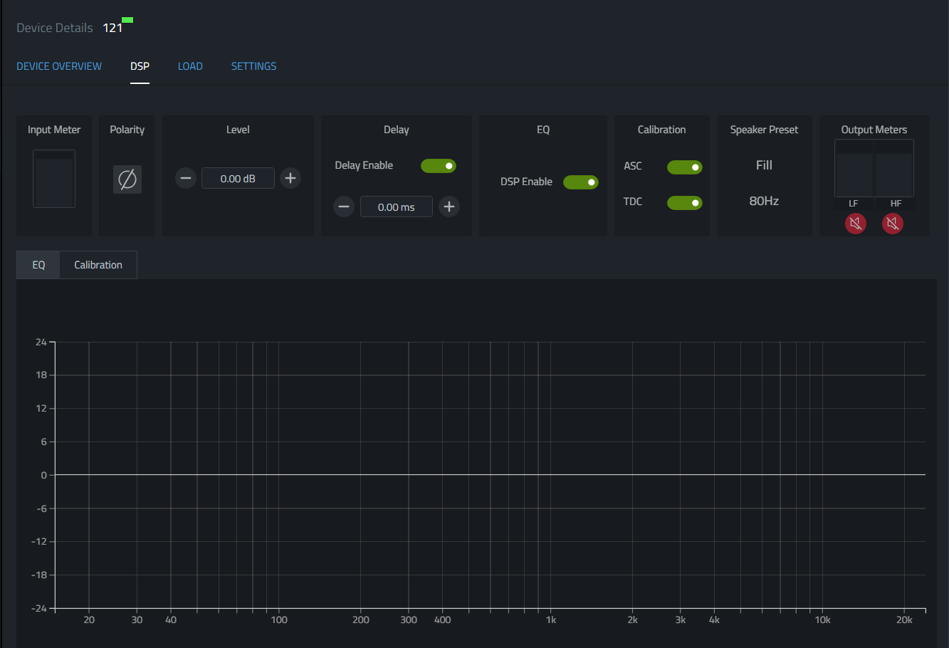
| Parameter | Description | Multi-Select |
|---|---|---|
| Input Meter | Shows input signal with Clip, RMS, and Peak meters. | Mixed values are shown as the highest value meter in the selection, calculated every 50 ms. |
| Polarity | This is a modifiable toggle that will invert the input polarity. See the Polarity View for more information. |
|
| Level | This is a modifiable field that is the actual gain on the device. It does not respect grouping when changed from the device panel. See the Gain View for more information. |
|
| Delay | This is a modifiable field that is the actual input delay set in the device. It does not respect grouping when changed in the device panel. See the Delay View for more details. |
|
| EQ DSP Enable | This toggle is modifiable and is only found in the Device Panel and on the device LCD. This toggles the EQ DSP enable. When disabled, the EQ section of the user DSP is completely bypassed. |
|
| ASC Enable | This toggles the enable for Array Size Compensation. This toggle does not respect grouping. For more information, see the Calibration View. |
|
| TDC Enable | This toggles the enable for Throw Distance Compensation. For more information, see the Calibration View. |
|
| Speaker Preset | This shows the selected output Preset Mode. From more information, see Speaker Preset View. |
|
| Output Meters | These show the output headroom of each bandpass. | Mixed values are shown as the highest value meter in the selection, calculated every 50 ms. |
| Band Pass Mute | Toggles the state of the mute for each bandpass. | Mixed values will introduce the  symbol. symbol. |
| Graph area |
|
The EQ and Calibration graphs are disabled when more than one device is selected. |
The Load Tab
The load tab provides access to individual devices internal Signal Generator.

If Multi-Selected, the most common value is displayed. Mixed values will introduce the symbol.
Settings Tab
The settings tab has access to parameters that can be modified when the device is connected. These parameters are read from the device when it is connected.
In Multi-Select states, the most common value is displayed. Mixed values will introduce the symbol. If any selected device is offline, all controls will be disabled.

Display Settings
| Parameter | Description |
|---|---|
| Auto-Dim | This feature dims the LCD to 0 after a specified time if no interaction on the device or event wakes the LCD. This can also be set from the LCD. |
| Auto-Dim Timeout | This is the duration of time the LCD remains on after an interaction or event wakes the LCD. This can also be set from the LCD. |
| Display Brightness | From 1-10, sets the brightness of the LCD back light. This can also be set from the LCD. |
| Lock Front Panel | This toggles a feature on the LCD that locks out all interactions from the LCD. This is to restrict changes on the device and is especially useful when the device is in a physical location where there is a risk of unauthorized changes being made. The lock will persist through a re-boot and can be disabled on the device by power cycling it while holding down the back button. |
Sleep Mode Settings
Auto Sleep allows the amplifier state to go to the lowest power state possible. The amplifier will come out of auto sleep after the input level passes the set threshold and will remain on until the level drops below the specified threshold for the specified time.
| Parameter | Description |
|---|---|
| Force Standby | Sets the device into a low power state where the amplifier, LEDs and LCD are turned off. This is a manual switch to remotely turn the device on and off |
| Auto Sleep Mode | Enables or disables the feature. This can also be set from the LCD |
| Auto Sleep Threshold | When the input signal drops below the specified threshold, the sleep mode timer will start. This can also be set from the LCD. |
| Auto Sleep Time | Specify the duration the level must be below the specified threshold before auto sleep is triggered. This can also be set from the LCD. |
| Auto Sleep Status | Indicates the state of the amplifier. Normal or Sleeping. |
Network Settings
All network settings are managed in NetSetter or on the device.
| Parameter | Description |
|---|---|
| Mode | Indicates DHCP or Static addressing modes. |
| IP Address | Indicates the reported IP address from the device. |
| Subnet Mask | Indicates the reported Subnet Mask from the device. |
| Gateway | Indicates the reported Gateway address from the device. |
| MAC Address | Indicates the reported MAC Address from the device. |